Okay so, this is the first time I've posted so here goes!
So I've recently began the install on my sound system in my new Activ and i thought i'd try and share some of my progress with you guys and see what you think, or if anyone has some suggestions.
Alright so what i'm attempting to do is use the existing head unit (its not Rockford nor MMCS). And I'm simply use a signal processor in the rear mounted on a stand that will also hold the two amps.
I'm upgrading the front and possibly the rear speakers and i'm interested in sound deadening also i'm going to be making mdf/fibreglass sub boxes for both sides.
So in other words I've got a bit of work in front of me, considering i use the car everyday its gonna be quite a challenge!!
So here's where i'm up to....
***** ALERT - Nominations for your new ClubCJ Committee can be made here *****
NSW / Zimmo / ...And it begins!
Moderators: Moderators, Senior Moderators
-
Zimmo
- Lancer Learner

- Posts: 5
- Joined: Sun Oct 14, 2012 8:43 pm
- Location: Central Coast, New South Wales, Australia
Part 1 - Running a power wire.
So i want to provide advice to anyone who is starting a project but also any advice any of the more experienced guys and girls out there could give me would be great!!
So The first step was the power wires, i was initially stumped, multiple searching on forums and studying the firewall led me to believe that i would have to drill into the left hand corner...
At this point it was a one month old car, so that wasn't gonna happen!
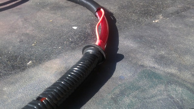
But then i found this:
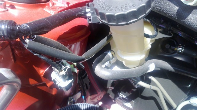
That doesn't look like much but behind the drivers side strut tower was a small grommet which when hollowed out is big enough to accommodate a 2 gauge wire.
And almost too easily that grommet came out just behind the drivers side kick panel, you'll have to remove the panel then peel the carpet back to be able to see it.
There is a spot in the felt that had already been cut so that it could be peeled away (i guess for use on a higher model) push that back and you should feel the grommet!
The wires were easy to route from here, it was simply a case of hollowing out the grommet then putting the wiring sheaths on.
The Sheaths weren't necessary but i thought that running through the car they would be easier to manage and less messy.
I decided to also run an extra wire because at this stage i wasn't sure if i would need it or not!
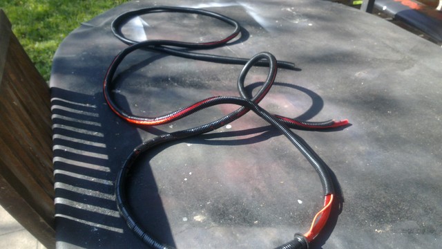
This bit you'll want to get right the first time, its a bitch having to take everything off again to widen a grommet that wont fit!
So that was sorted, the easiest way to route the wires through the engine bay i found was to follow the factory loom which runs parallel to the firewall in the top corner
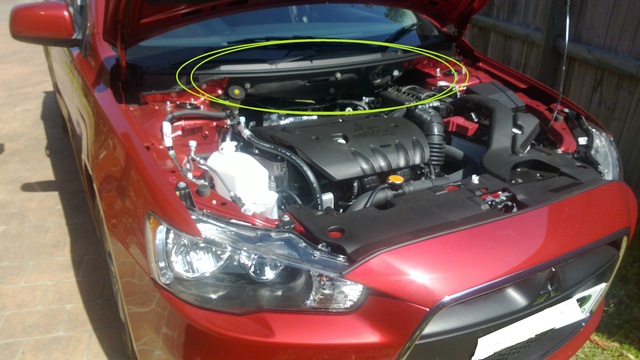
By keeping it as tucked away as possible to the factory wiring, it gives it the least possible chance of being caught in the engine or melting.
Now i haven't attached it to the battery as of yet so i don't have any pictures of where to put the fuse but it should fit nicely somewhere near the oem fuse box.
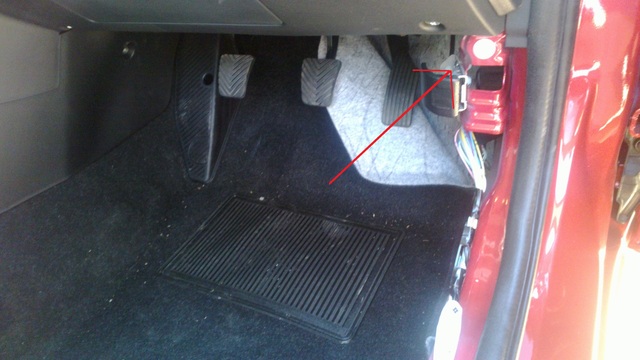
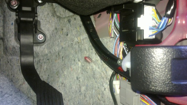
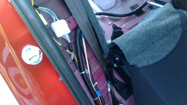
Inside the car was easy, i ran the wires directly down the hood release line then down. I used as many cable ties as i could so that i didn't have wires grabbing at my foot pedals!
Mitsu provides handy clips to keep everything in check they also help keep the wire from going slack so i pretty much run it through to the back in a minute or so.
I Just had to remove the seats the rear panels, the scuff panels (front and rear) and finally the b pillar panel.
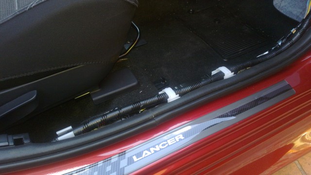
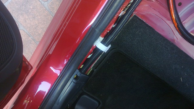
Finally i ran the wires up the rear wheel well and then they pop out through the boot lining!
Too easy!
So The first step was the power wires, i was initially stumped, multiple searching on forums and studying the firewall led me to believe that i would have to drill into the left hand corner...
At this point it was a one month old car, so that wasn't gonna happen!
But then i found this:
That doesn't look like much but behind the drivers side strut tower was a small grommet which when hollowed out is big enough to accommodate a 2 gauge wire.
And almost too easily that grommet came out just behind the drivers side kick panel, you'll have to remove the panel then peel the carpet back to be able to see it.
There is a spot in the felt that had already been cut so that it could be peeled away (i guess for use on a higher model) push that back and you should feel the grommet!
The wires were easy to route from here, it was simply a case of hollowing out the grommet then putting the wiring sheaths on.
The Sheaths weren't necessary but i thought that running through the car they would be easier to manage and less messy.
I decided to also run an extra wire because at this stage i wasn't sure if i would need it or not!
This bit you'll want to get right the first time, its a bitch having to take everything off again to widen a grommet that wont fit!
So that was sorted, the easiest way to route the wires through the engine bay i found was to follow the factory loom which runs parallel to the firewall in the top corner
By keeping it as tucked away as possible to the factory wiring, it gives it the least possible chance of being caught in the engine or melting.
Now i haven't attached it to the battery as of yet so i don't have any pictures of where to put the fuse but it should fit nicely somewhere near the oem fuse box.
Inside the car was easy, i ran the wires directly down the hood release line then down. I used as many cable ties as i could so that i didn't have wires grabbing at my foot pedals!
Mitsu provides handy clips to keep everything in check they also help keep the wire from going slack so i pretty much run it through to the back in a minute or so.
I Just had to remove the seats the rear panels, the scuff panels (front and rear) and finally the b pillar panel.
Finally i ran the wires up the rear wheel well and then they pop out through the boot lining!
Too easy!
Last edited by Zimmo on Mon Oct 15, 2012 9:23 am, edited 1 time in total.

how big are your amps.
in my professional opinion its much more economical to utilise the huge space under the front seats for amps and processors.
also, behind the OEM deck in the dash there is a bucket load of space to hide things.
or if your processor is adjustable, using the space in front of the gear stick is an option as well to put stuff (look in my profile and see what i put there)
CLUB CJ CAR AUDIO VENDOR
Owner and Builder of Australia's LOUDEST STREET LEGAL Lancer 147.5dB
2013 WORLD TITLE
2012 QLD State Champion
2008 Australian Champion

Owner and Builder of Australia's LOUDEST STREET LEGAL Lancer 147.5dB
2013 WORLD TITLE
2012 QLD State Champion
2008 Australian Champion
-
Zimmo
- Lancer Learner
- Posts: 5
- Joined: Sun Oct 14, 2012 8:43 pm
- Location: Central Coast, New South Wales, Australia
Thanks for the advice!
Right now ive actually just put the mount for the amps in, i was seriously considering the seats as a mounting place, didnt even consider behind the HU
Do you think that running all these wires to the boot (ie power on one side and the signal on the other) then having the speaker wires coming back is a big risk for noise?
Oh and its one 1000W Kicker and an 800W Rockford amp i'm using
power and signal should always be kept seperate.
1000w and 800w... but what rms?
people look in my car and see 2x 6000w mono amps and think "holy crap" but then i tell them the RMS value (7200rms) and they calm down a little lol
1000w and 800w... but what rms?
people look in my car and see 2x 6000w mono amps and think "holy crap" but then i tell them the RMS value (7200rms) and they calm down a little lol
CLUB CJ CAR AUDIO VENDOR
Owner and Builder of Australia's LOUDEST STREET LEGAL Lancer 147.5dB
2013 WORLD TITLE
2012 QLD State Champion
2008 Australian Champion
Owner and Builder of Australia's LOUDEST STREET LEGAL Lancer 147.5dB
2013 WORLD TITLE
2012 QLD State Champion
2008 Australian Champion
thats understandable lol
kicker under rate their amps. in the box is a birth certificate stating what the tested RMS value is
but remember, they do it all at 2ohm, not 4ohm
so when u go to match subs to the amp.... 95% of subs are 4ohm
kicker under rate their amps. in the box is a birth certificate stating what the tested RMS value is
but remember, they do it all at 2ohm, not 4ohm
so when u go to match subs to the amp.... 95% of subs are 4ohm
CLUB CJ CAR AUDIO VENDOR
Owner and Builder of Australia's LOUDEST STREET LEGAL Lancer 147.5dB
2013 WORLD TITLE
2012 QLD State Champion
2008 Australian Champion
Owner and Builder of Australia's LOUDEST STREET LEGAL Lancer 147.5dB
2013 WORLD TITLE
2012 QLD State Champion
2008 Australian Champion
-
Zimmo
- Lancer Learner
- Posts: 5
- Joined: Sun Oct 14, 2012 8:43 pm
- Location: Central Coast, New South Wales, Australia
Part 2 Signal Wires
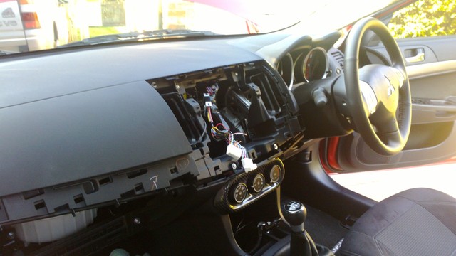
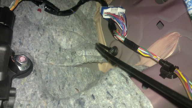
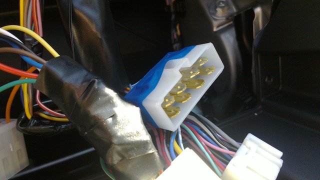
This is how step 2 began with my dash in a million pieces, i needed to get to the 8 speaker wires coming out of the stock unit.
As i mentioned before, i'm using the head unit that comes standard, and i was wary about using a new unit.
Always disconnect your battery first!!
Basically from the stock connector i ran the speaker wires into a set of 2 aftermarket 8 pin connectors,.
The Connectors can be switched so that for the moment i can continue using my speakers (Stock Mode), then in the future i can switch it over by simply swapping plugs!
Also i 'split' the signal from the rear channel to use for a sub-woofer channel on my signal processor.
These four wires for the sub are always connected regardless if the connectors are in 'Stock Mode' or otherwise!
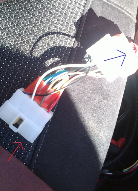
(On this photo Red is IN & the Plug with the blue arrow is the one that can be swapped!)
This is The Guide i used, the first colours are the factory wires, the second being the colours i chose for the run to the back of the car
Front Right
+ White/Red =Red
- Black/Red =Brown
Front Left
+ White/Blue = White
- Black/Yellow= Black
Rear Right
+ Yellow/Red = Orange
- Grey/Red = Yellow
Rear Left
+ Yellow/Blue = Blue
- Grey/Blue = Green
Subwoofer Right
+ Yellow/Red = Orange/Grey
- Grey/Red = Yellow/grey
Subwoofer Left
+ Yellow/Blue = Blue/Grey
- Grey/Blue = Green/Grey
NOTE: THIS IS ONLY A GUIDE PLEASE VERIFY IF YOU HAPPEN TO USE THIS AS A REFERENCE!
Alright so then finally came time to chop the wires or as i thought 'The Scary Bit'
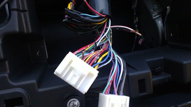
As you can see i was cutting max 2 wires at a time and using a AA battery to test that i had snipped the corresponding (+&-) wires.
All i had to do was crimp the connector pins to the ends of the freshly cut wires then plug them into opposite sides of a standard 8 pin connector.
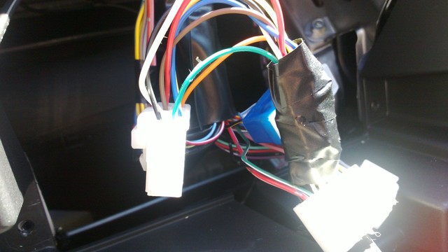
Sorry about the quality of these photos, the harness with the messily taped wires is factory and as you can see it matches the blue harness so that i could simply plug it in and nothing would have changed.
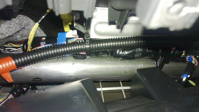
It was simply a case of plug and play with my pre wired connectors and finally routing the wires to the back via the passenger side of the car!
-
mattywired
- Lancer ES/EX

- Posts: 172
- Joined: Wed Aug 01, 2012 2:09 pm
- Location: Penrith, NSW Australia
Who is online
Users browsing this forum: No registered users and 71 guests